Avoiding Header-Aches

As I started thinking about putting in the structural walls to support the floor joists, which need to go in before the second floor can be built, I started to agonize about certain aspects of the design that hadn’t really captured my attention before.

There are two areas on the original plans where very long (eight to ten feet long) “headers” (structural supports over openings) were needed to bridge over open areas: over the kitchen (shorter span, and less weight to bear) and above the two angled bedroom doors (longer span, and greater weight).  I wanted to keep these headers limited to 2×8 members, so that they wouldn’t have to drop down significantly into the living space, but there are limits to what even a triple 2×8 can span and still provide sufficient structural support.
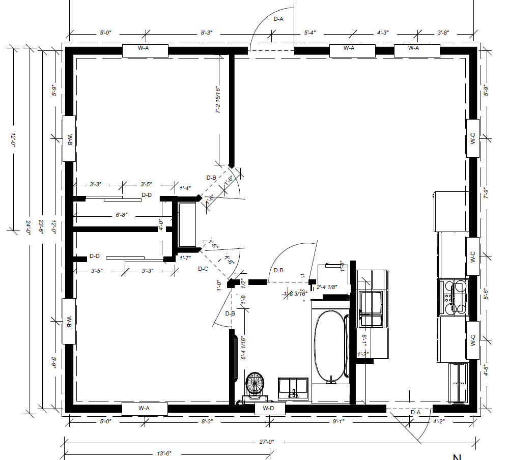
Floor Plan Before Wall Adjustments

And then I found myself wondering why I had wanted those slanted doors in the first place.  I mean, they’re harder to build, they take away from the floor space in the bedrooms, they don’t actually add useful floor space to the living room… they just seemed like a bad idea all around.  Could I adjust the plan so that the doors were straight along the wall, thus providing a space between them where a vertical support (“jack stud”) could support the header?

One question led to another and pretty soon I was rethinking a lot of different things.  What did I really want to do for loft access?  Where would it go?  Was the area I had carved out for the washer/dryer actually the right size?  Were the closets the right size and optimally placed?  Did I need three doors within a few feet of each other around the bedroom and bathroom?  In the end I made a lot of relatively small adjustments, but several that I think are reasonably significant.

Raederle answered the question about the three doors with a resounding “yes”: given that the bedrooms open out onto the living area, it’s really important that at least one of the bedrooms offer a path to the bathroom without going into the common space.  Imagine your kids have guests over and you’ve slept in… do you really want to have to put clothes on to get to the bathroom in the morning?

We decided that the aesthetic of a spiral staircase would add a lot of appeal to the interior design.  This would take more floorspace (12-15 sq ft) than a drop-down attic stair (8-10 sq ft) but a whole lot less than a conventional staircase (33 sq ft), and despite the cost it would probably be worth the difference in making a more pleasant and usable space.  The placement of this couldn’t be after-the-fact, since it would have to come in to an area where the ceiling height was at least 7′ (a maximum of 18″ south and 48″ north of the centerline).  In the end, it pushed the doorway of the second bedroom to the south end of the wall.  (One can argue that this slightly improves egressibility since it opens out right onto where the back door is located.)

I tried adjusting the closets to go adjacent instead of back-to-back.  However, this created issues with the placement of the BR1-LR door and with ensuring the accessibility of the bathroom, and so instead I just stretched out the wall between them.  The combination of the door and closet placement now means that BR2 could more easily accommodate two twin beds, by poking one into the corner created by the closet.

A little fine-tuning on the loft design now brings the northern loft area further out over the kitchen, which gives better access to the west wall window in the loft.  (I may also take advantage of this to increase the kitchen cabinet sizes a bit on the right of the sink, though I haven’t addressed this in the design.)  There’s a small area between the staircase and the bathroom where the loft floor meets the staircase platform which is actually cantilevered out, but it’s under 2′ long and I don’t think it will be aesthetically objectionable since it’s at ceiling height.

I ensured that the washer/dryer space was big enough for the larger (4.3 cu ft) unit rather than the smaller (2.8 cu ft) unit that I had originally projected; this means it will fit a wider range of solutions.

I adjusted the west wall of BR2 to be a 6″ wall instead of a 4″ wall, to provide extra structural support for the flooring and make it easier to route mechanicals.  This wall is intended to come in partially overlapping the steel I-beam in the floor, so that it’s easy to route mechanicals to the side of the I-beam, while still being able to bear most of the weight directly on it.

Below is the resulting changed plan.  It probably doesn’t look much different unless you’ve been spending as much time thinking about this as I have… but it means that there are no headers on the west bedroom wall that exceed the width of a door, and the header over the kitchen falls into the range where three or four 2×8’s can easily provide the required support.

I needed to get this nailed down because one of the next steps is to actually lay out the placement of these walls on the subfloor, so that I can begin constructing the structural walls and then complete the rim joists and floor joists of the second floor.
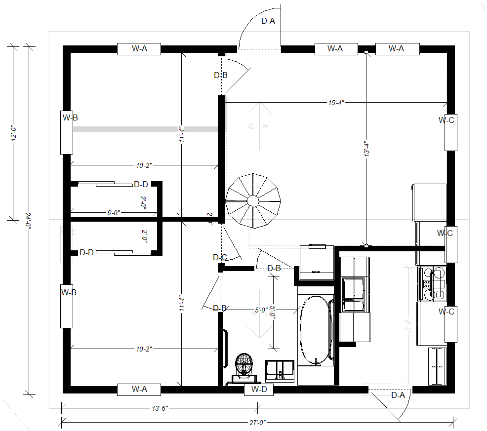
Floor Plan After Wall Adjustments

And Now, Your Feature Presentation

I’ve been gradually building up a summary of the main features that I plan to include in the Little Rental House.  Some of these will go in with the first build; others might be “nice-to-haves” that get added once the home is actually ready for occupancy.

  • Accessible
    • ADA-compliant parking space
    • ADA-compliant bathroom, kitchen, living areas
    • ADA-compliant entrance ramps, etc.
  • Efficient resource use for heating and cooling
    • Walls, ceiling, and floor all insulated to better than R-40.
    • Double (or maybe triple) glazed windows for heat retention.
    • Heated with air-source heat pump to minimize power required.
    • Heat-recovery ventilator to provide fresh air with minimum heat loss.
    • Hot water heating inside heated space (reduces heat loss)
    • Drain water heat recovery unit
  • Minimum water footprint
    • Rainwater collection with filtration and UV sterilization
    • Downcycling of greywater for toilet flushing
  • Minimum power requirements
    • Low-voltage LED lighting used throughout to save power (< 0.25kWh/day)
    • DC refrigerator (< 0.7kWh/day)
    • Direct outlets for DC appliances (24V, 5V USB)
    • Two stage water heating with ultra-insulated storage (30 gal, est. < 0.5kWh/day) plus on demand system for large volume use (AC only)
    • Water pumping using low power, low voltage DC pumps (< 0.1kWh/day including sterilization)
    • Heat recovery from waste water (bathtub, clothes washer, sinks)
  • Grid-flexible solar power generation
    • Battery storage (about 10 kWh) for approximately 6 days including hot water, up to 2 days with constant heating.
    • Online inverter provides whole-house “uninterruptible” power supply

The City of Ithaca and Town of Ithaca are working on a new joint “energy code supplement” to encourage green building.  New construction should get a minimum of 6 “points” in their system.  My rough calculation for the proposed home is 11 points:

  • EE1: air source heat pump = 3 points
  • AI1: smaller building size = 2 points (under 1120 sq ft)
  • AI2: heating system in heated space = 1 point
  • AI5: modest window-to-wall ratio (13%) = 1 point
  • RE1: on-site renewable electric = 3 points (2350 kWh/year / 648 sf > 3.6)
  • OP4: meet NYStred Code-2020 Version 1.0 = 2 points (maybe, complex to evaluate)

SIP Sliding Away

This week, I threw up my hands in frustration and did a small redesign.  I have been planning all along to use SIPs for the first floor flooring (above the basement).  Unfortunately, I have been so busy with other projects like fencing our back yard against deer and dealing with my duties as volunteer Treasurer for my community, that I didn’t actually get an order placed.  Add to this that the time frame for getting SIPs delivered turned out to be 3-4 weeks ARO (“after receipt of order”), this would have put me receiving the materials somewhere around when the average daily high temperature crosses below 50°F/10°C and the snow starts to fly.  Plus, the quotation came in about $2,000 over my budgetary estimate.  I could save some of this by using a lower insulation SIP – which would probably be OK – as the basement will generally stay closer to ground temperature than outdoor temperature, I won’t lose as much heat through the floor as through the walls.

The local code enforcement officer indicated that I needed to either get a floor in place or put up a (rather permanent-sounding) fence around the site before the winter, and I didn’t want to spend a whole lot of money on fencing if I could just get the floor on.

To top it off, I was having trouble getting a useful structural load analysis that reflected my intended usage.  Somewhere in here, while I was busy trying to compute the transverse load for a 4′ span from the modulus of elasticity of extruded polystyrene, I turned a corner.  Was this really worth going out on a limb and then jumping from treetop to treetop over?  Load tables and beam strength calculations for wooden joists were incredibly easy to come by.  And they showed that all it would take was a 2×6 member spaced every 24″1 to span over 8 feet.  Heck, even a measly 2×4 would span 5 feet.  If these were then reinforced with a bottom layer of plywood (which would effectively prevent the bottom of the beams from stretching and make them even stronger) and topped with subflooring, I would have a structurally sound flooring solution.

It would need to be insulated though.  Polyisocyanurate foam board (often abbreviated PIR) is about the best insulation density you can get in an off-the-shelf product (R-6.5 per inch) and so 4 inches of this would put me at R-26 – exactly where the cheaper SIPs would have put me.  However, that would involve a lot of cutting foam to fit around the structural members.  I was also worried about the thermal bridging from all of the wood, particularly if I needed to space the joists 16″ OC to ensure a rigid floor and not need multiple layers of subflooring to achieve it.

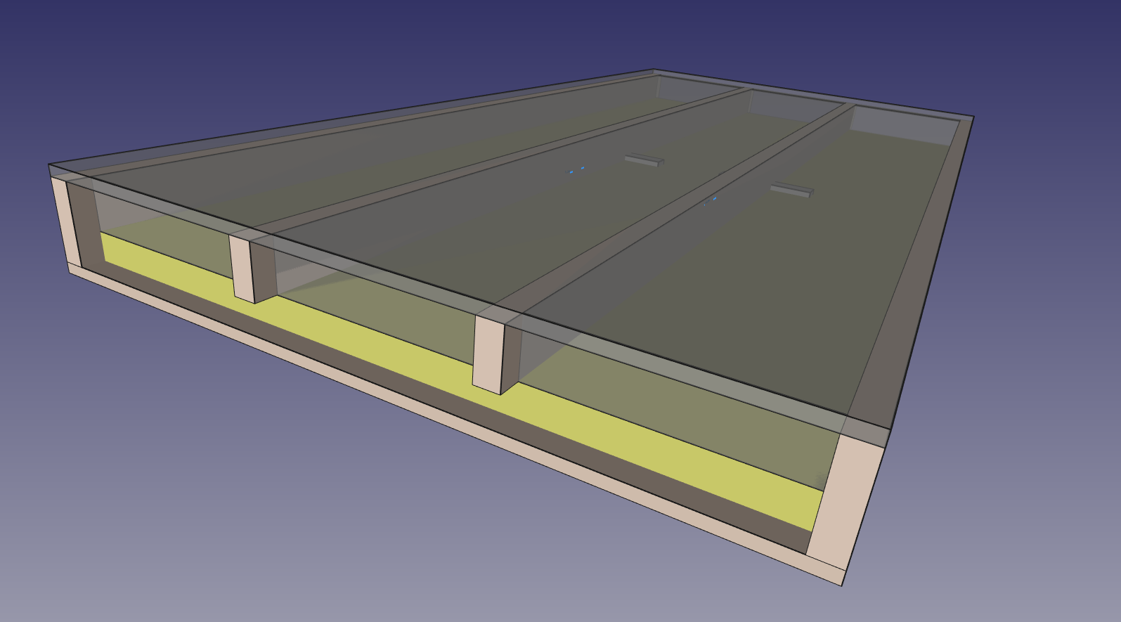
I finally came up with what seemed like the key innovation to me.  If a 2×4 can span over 5′ at 24″ OC or nearly 6′ at 16″ OC, then as long as it’s structurally supported every 4′ or 5′, the 2×4 can actually serve the role as a floor joist.  Adding a 2×6 for every 3rd member would increase the strength further.  The PIR foam board I was looking to use2 is 2″ thick, meaning that it would in principle fit in the difference between a 3.5″ 2×4 and a 5.5″ 2×6, and from there it would actually provide some additional support to the 2×4.  At this point I could get away with only cutting each PIR board a little bit to fit between 2×6 members, and around the supports.

But now I’m only at R-13!  That isn’t very good insulation for a potential 25°F/14°C temperature differential.  Adding batts of 3.5″ rock wool, which is exactly designed for 2×4 spaces, adds another R-15 (total R-28).  The final assembly looks something like what is shown here.

And, I should be able to start getting the parts more-or-less immediately.  And, the whole thing will probably save me some money relative to even the cheapest of the SIPS.  Some extra labor, to be sure, but the sooner I can get started on it, the more likely I am to get this done before real winter hits.

A little afterword about the R-value.  Using data on individual components I’m estimating the average R-value for the entire floor at 25.9.  It’s interesting to see that 77% of the heat loss is through the two layers of insulation; 14% of it is through the 2×6 joists; and 8% of it is through the 2×4 joists.  Thus even though the 2×6 joists account for less than 5% of the total area, they’re responsible for a significant fraction of the heat loss.  If I had used 2×6 everywhere, the R-value would have been lowered to 23.6 (almost 10% worse) and the joists would have been 30% of the loss.


  1. The construction terminology is 24″ OC standing for “on center” – that is, the centers of the boards are 24″ apart.
  2. I don’t really care for Dow but the appears to be the only suitable PIR I can get locally.

Making Plans – The Road Ahead

I’ve decided to upload a full copy of the plans for the Little Rental House, for those who might be interested in seeing more details.  When I was first designing, I found that most house plans out there were behind a paywall.  Since I drew these plans myself, there isn’t any reason I can’t share them with the world, but if you find them useful I’d be happy if you wanted to make a donation that you feel reflects the value you’ve gotten from them.

I’m including some notes below, and as I have time to write up more aspects of the project, I will try to update this page with links to more detailed posts.

E – 1: Elevations

The original design work was done in an extremely old 3D Home Architect (version 10) from Punch Software.  While it has plenty of limitations and occasional crashes, the mere fact that it still loads and runs under Windows 10 is so gratifying that I’m willing to put up with a few glitches.  This allowed me to trivially create the 3D renderings shown on the first page.  They’re pretty, but they don’t necessarily communicate the technical details needed for construction.

F – 0: Basement

I’ve written about the choice to include a basement in this blog.  The elevator speech I give people when they look at the big hole in the ground and say “oh, it’s going to have a basement?” is: Well, yes, but it’s really just for mechanicals.  It turns out it’s about the same cost to build a basement where I can do the other work myself, as it is to build a slab and hire people to do all the work that has to get done perfectly the first time before concrete is poured.  Plus, it allows me to add some features like waste water energy recovery that I wouldn’t have room for otherwise.

On the technical side, I’ve elected to go with cast-in-place walls for cost, making them 8″ thick so there is plenty of “bearing space” for the I-beams that constitute my floor supports.  These will run underneath the SIP flooring to provide a relatively low cost and low labor support structure that will prevent floor sagging.  I may at some point share some of the details of the engineering calculations for the beam strength here, but the short form is that spanning 24′ with wood would require huge timbers or manufactured wood beams that are much more expensive and not much more renewable than iron, and splitting the distance with a single 27′ beam and 12′ joists would have more susceptibility to the kind of “droop” that I’m experiencing in my own home, where doors need to periodically be adjusted so they latch properly.  It seems like steel beams are rarely used in residential construction, but I’m not entirely sure why not.

I explored the use of precast stairs, but found out that the maximum opening they would allow is 39″ wide, which would significantly limit the size of tanks and other items I might want to move into the basement.  It would also potentially need to be longer than the 6’4″ shown on the plans, which would make the stairs at risk of coming too close to the lot line.  Bilco’s standard “Size C” door will allow for a full 4′ wide staircase, which I’ll then have to build.

F – 1: First Floor

Because I’m building an accessible home, all the living areas are on the first floor.  Two bedrooms of 100 sq feet take up the east; an accessible bathroom is centered on the north wall; a large living/dining room area is at the southwest, and a small galley kitchen begins just after the front entrance at the northwest.

The layout optimizes the appliances that need water and drains (kitchen sink, bathtub, bath basin, toilet, and clothes washer) within a very small area, which will reduce the heat losses for hot water and the overall plumbing materials cost.  The stove is at the outside edge to allow it to be directly plumbed with an external propane tank.1

F – 2: Second Floor

This floor represents an L-shaped area of extra floor space.  It won’t be accessed by stairs, but rather by a ladder of some sort.  Some might choose to use it for storage, others as a play area for kids (it will have a railing around it), and others as an office.  Because it’s not accessible like the first floor, I didn’t want it to have any necessary functions, but getting a good roof slope for solar more or less automatically produces a space here and I thought many would find it useful.  There’s a small area at the southeast that is so low (below head height even for kids) that it’s not useful floor space, but some mechanicals (such as a heat-recovery ventilator) could conveniently be installed here.

M – 1: Electrical

This sheet shows the placement of various electrical fixtures on the first floor.  It includes the placement of various low voltage LED lights, low voltage (24VDC) electrical outlets, and the conventional 120V outlets and switches as required by code.  What it does not specifically cover is how the outlets and switches are wired to two different service panel – a primary 150A service panel and an auxiliary smaller (probably 60A) subpanel for “critical loads” which can be supplied from a solar battery bank inverter.  I’ll write about these details in a separate blog post.

S – 1: Sections

These fun little details show cross-sections of three portions of the design: the roof, the basement wall and first floor, and the slab/footer.  The roof details show how the different layers of insulation (which together add up to approximately R-53) are installed, which prevents condensation within the cellulose insulation.  The basement wall details show the relationship between the footer, footer drain, basement slab, wall, backfill, I-beams, SIP flooring, and SIP walls.  These details help identify how the structural components work together and also identify particular elements which need to be purchased and installed such as the “mud sill” and “rim joist” boards.  Finally the slab/footer NEC detail reflects the (relatively new) requirement that portions of the foundation which are in electrical contact with the ground must now have their own ground connections, in addition to the normal requirements for grounding rods.

W – 1: Schedules

This shows the window and door “schedules” that list the particulars of the windows and doors to be installed in each location.  Although I’ve listed preferred manufacturers here, this piece of the design isn’t 100% set in stone as the availability of different windows from different companies seems to vary a lot over time.  One of the key elements is the fact that the bedrooms must have “egressible” windows with a significant clear area (5.7 ft²) through which residents can evacuate and/or firefighters can enter.  In addition to the mandatory egressible window in each bedroom, I’ve also included one “E1” window in each bedroom, which meets the requirements only on the first floor (clear area 5.0 ft²).

N – 1: Notes

This page covers a lot of technical details which are better stated in text than in drawings, ranging from the general “do the work according to code” to details like the structural lumber stress values and the requirements for smoke and carbon monoxide detectors.

  1. I’m not thrilled with the use of propane, but it provides a backup in case electric energy winds up being in short supply.  At present, propane is produced in surplus as a side effect of oil drilling, and when there isn’t a market for it, it is often flared off.  So by using it I’m choosing to put that heat somewhere useful instead of making it a waste disposal process.