I’ve decided to upload a full copy of the plans for the Little Rental House, for those who might be interested in seeing more details. When I was first designing, I found that most house plans out there were behind a paywall. Since I drew these plans myself, there isn’t any reason I can’t share them with the world, but if you find them useful I’d be happy if you wanted to make a donation that you feel reflects the value you’ve gotten from them.
I’m including some notes below, and as I have time to write up more aspects of the project, I will try to update this page with links to more detailed posts.
E – 1: Elevations
The original design work was done in an extremely old 3D Home Architect (version 10) from Punch Software. While it has plenty of limitations and occasional crashes, the mere fact that it still loads and runs under Windows 10 is so gratifying that I’m willing to put up with a few glitches. This allowed me to trivially create the 3D renderings shown on the first page. They’re pretty, but they don’t necessarily communicate the technical details needed for construction.
F – 0: Basement
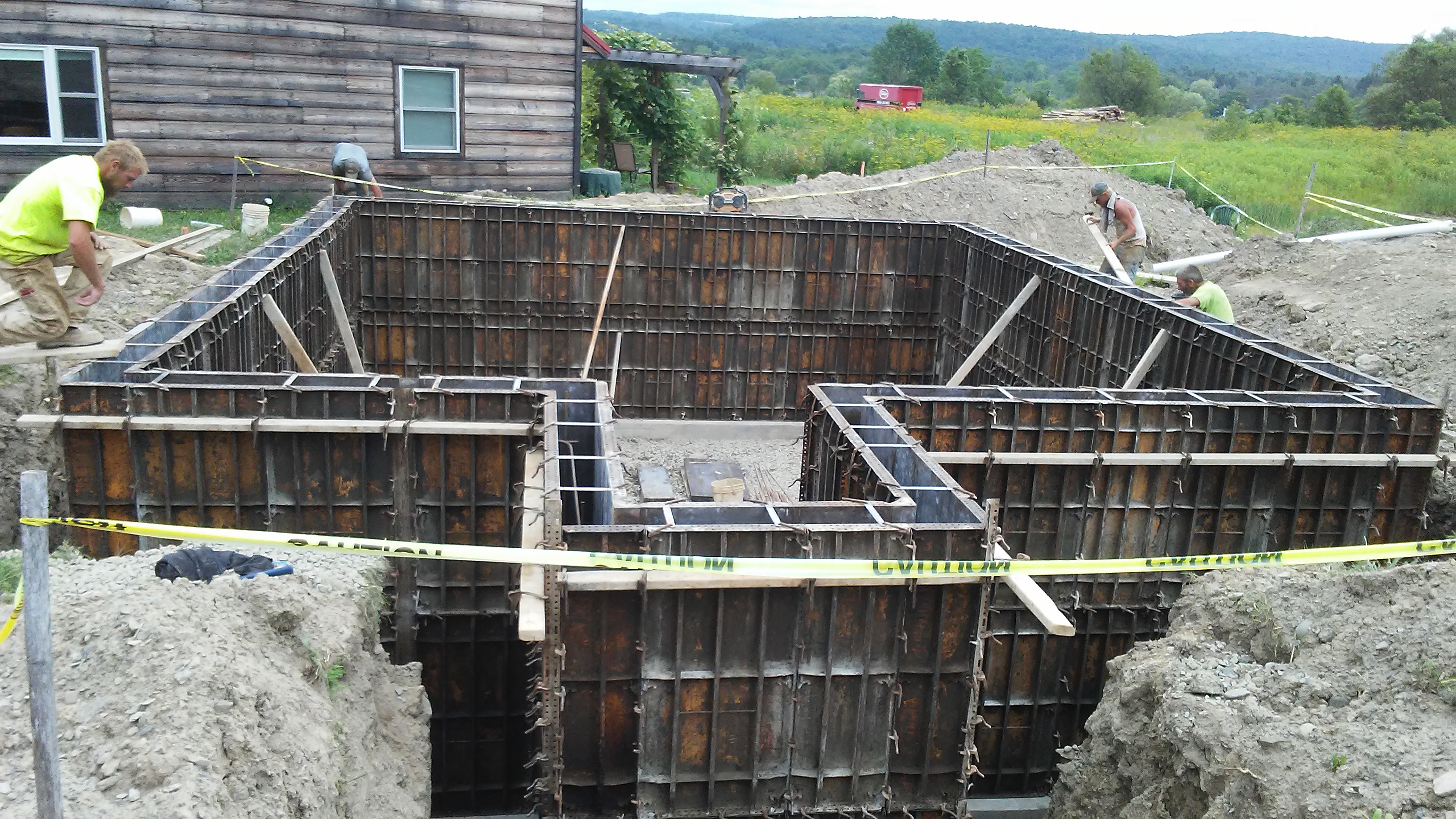
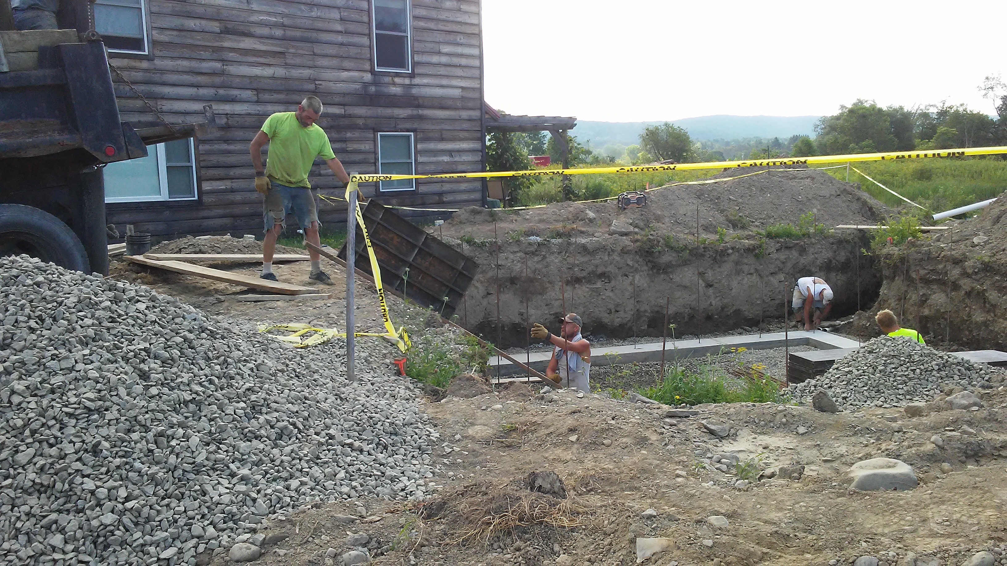
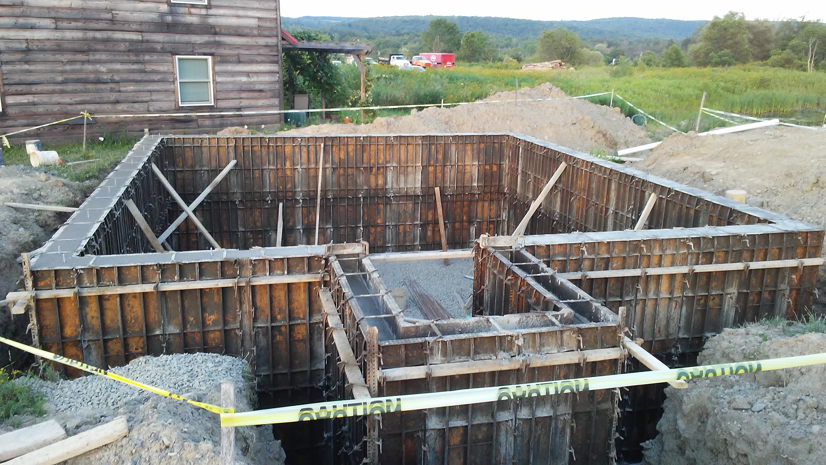
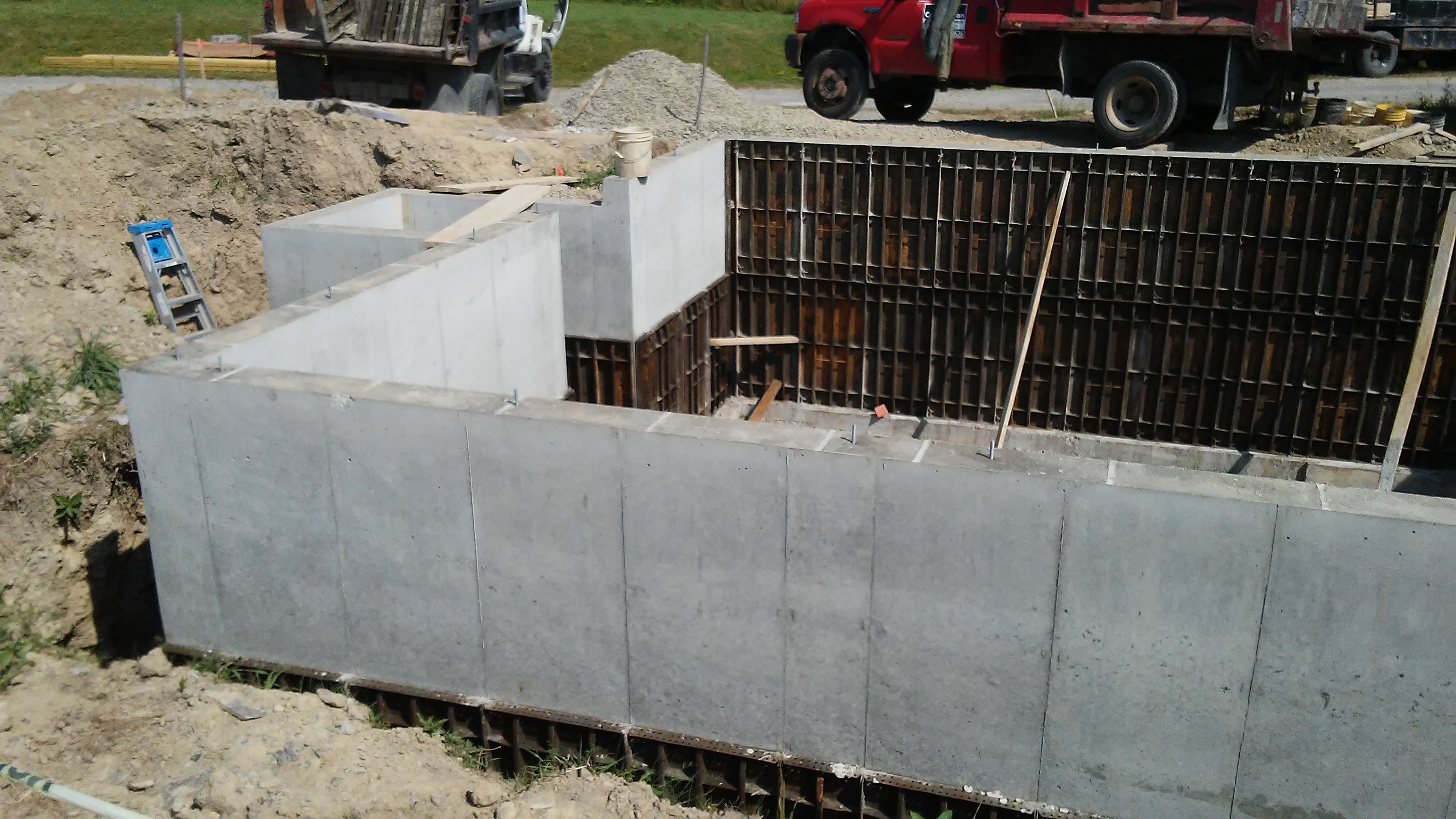
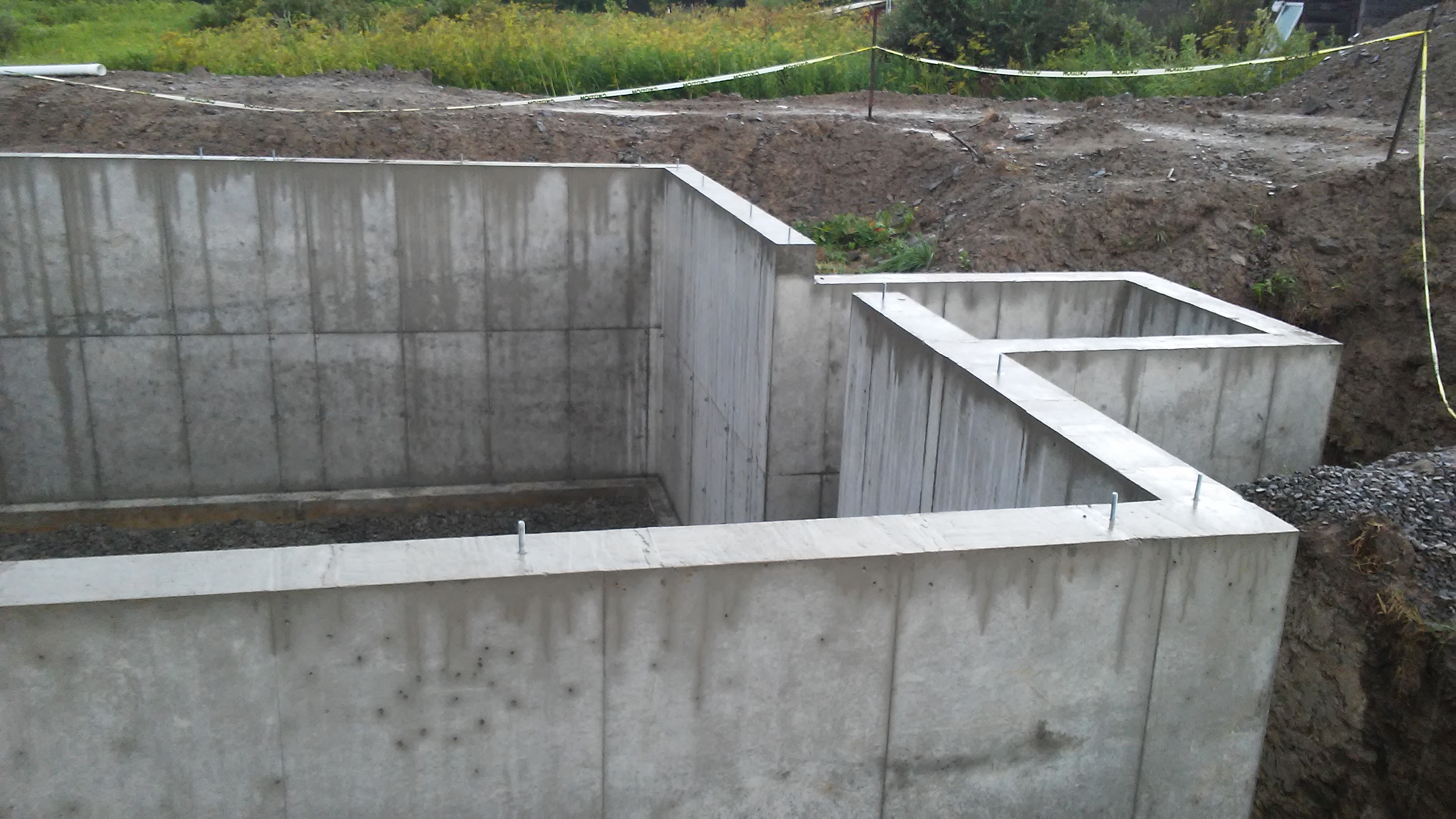
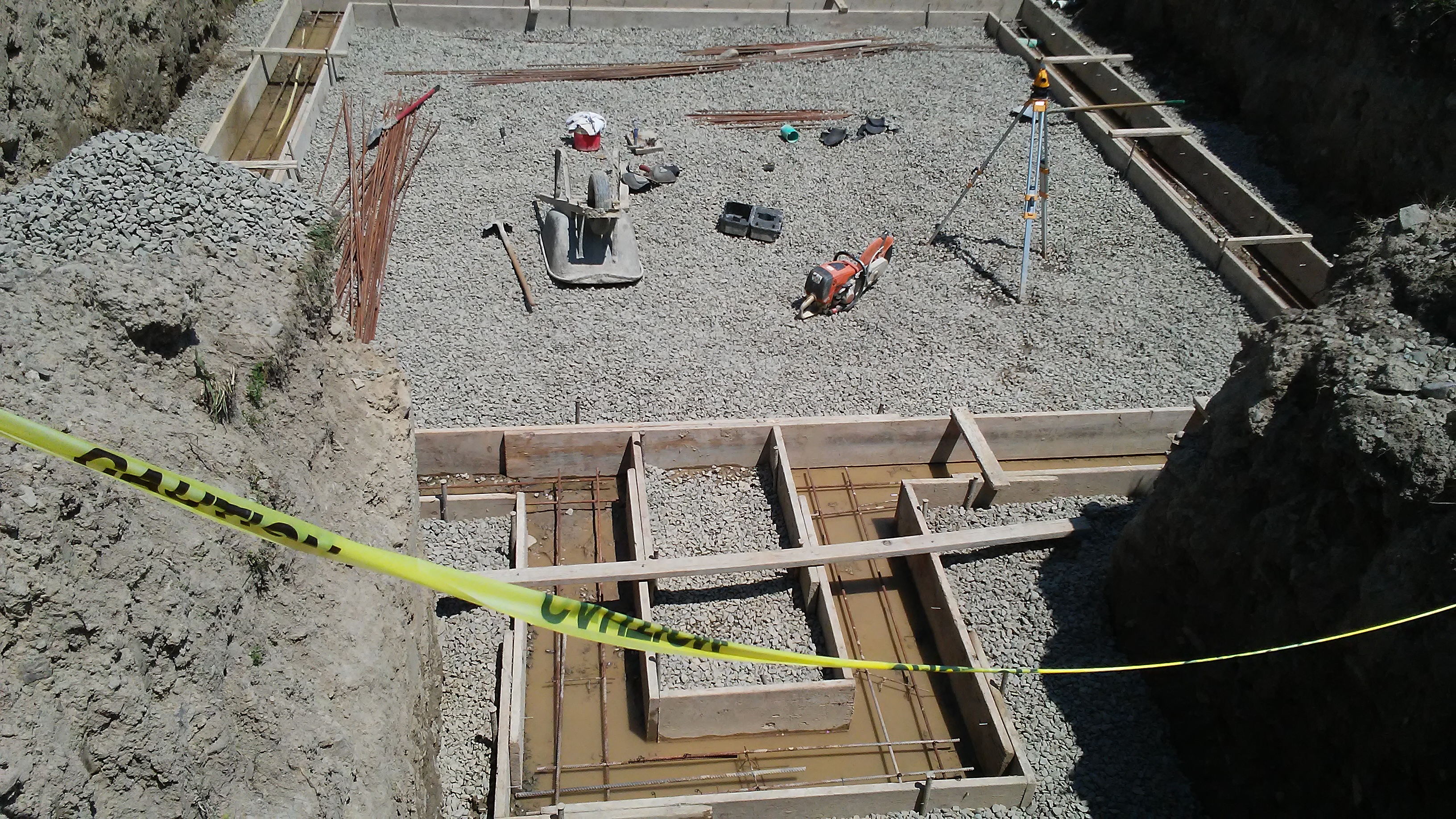
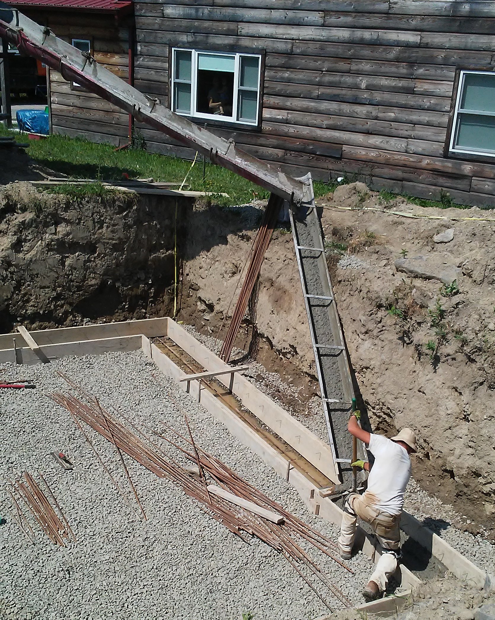
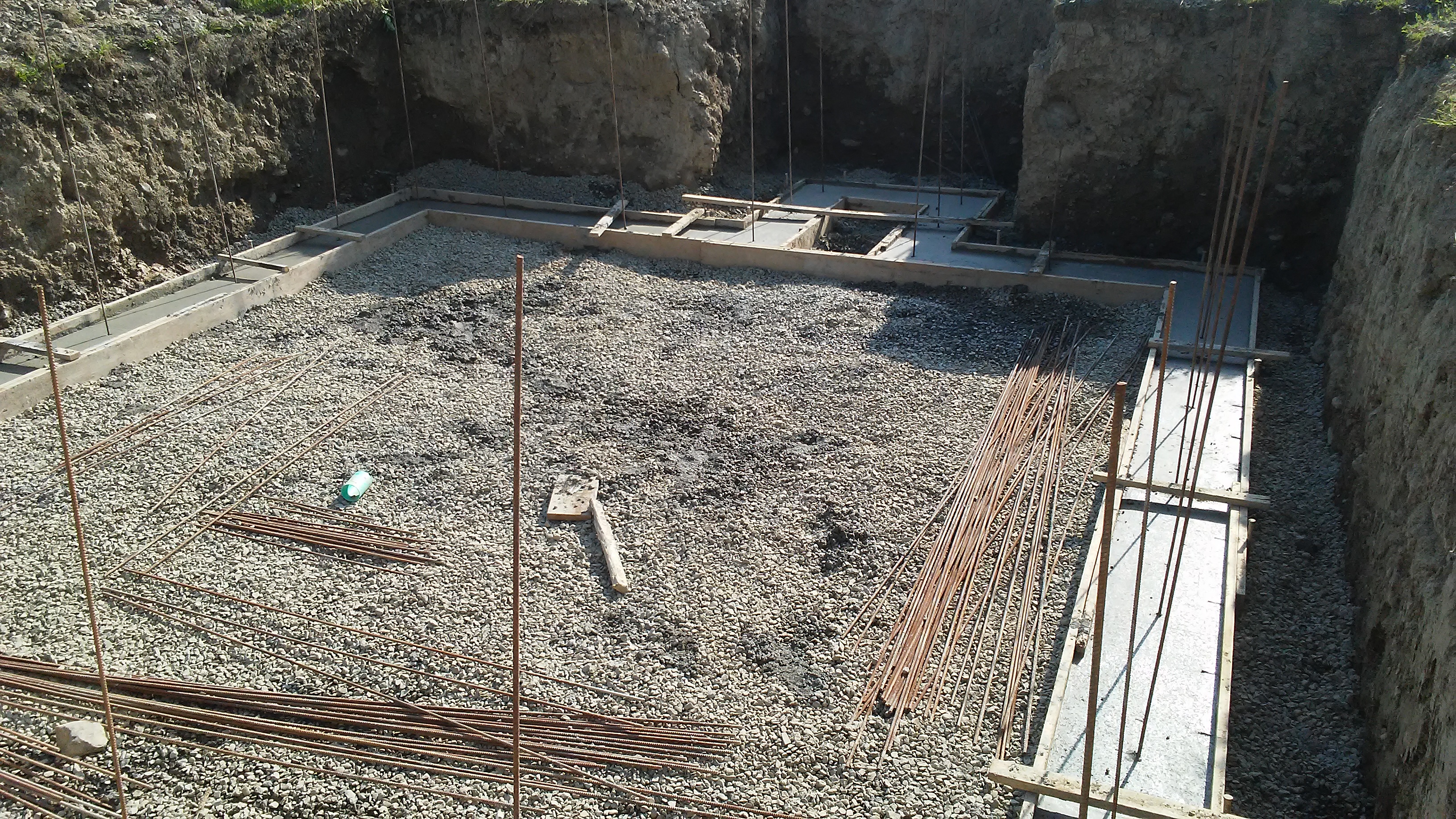
I’ve written about the choice to include a basement in this blog. The elevator speech I give people when they look at the big hole in the ground and say “oh, it’s going to have a basement?” is: Well, yes, but it’s really just for mechanicals. It turns out it’s about the same cost to build a basement where I can do the other work myself, as it is to build a slab and hire people to do all the work that has to get done perfectly the first time before concrete is poured. Plus, it allows me to add some features like waste water energy recovery that I wouldn’t have room for otherwise.
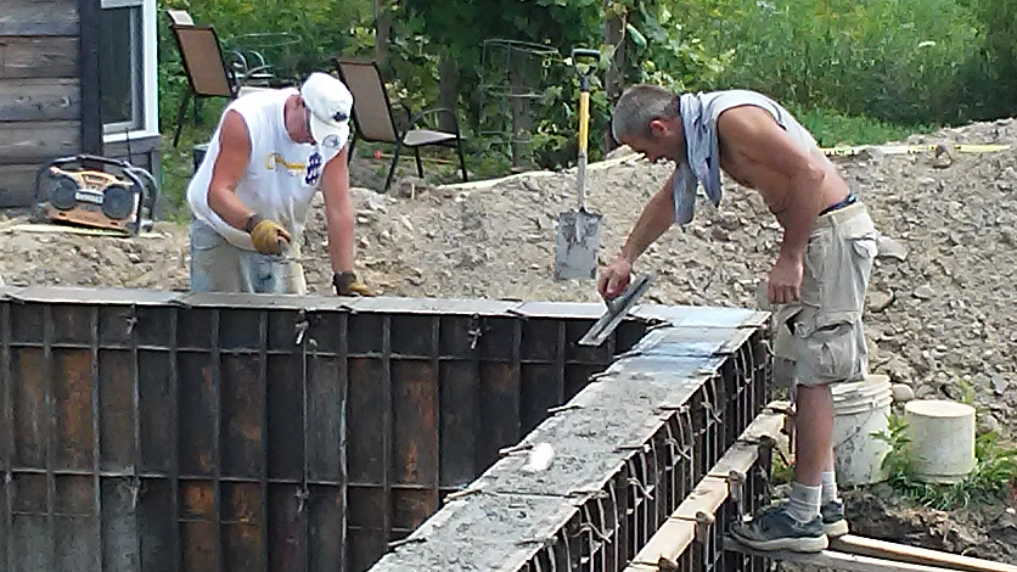
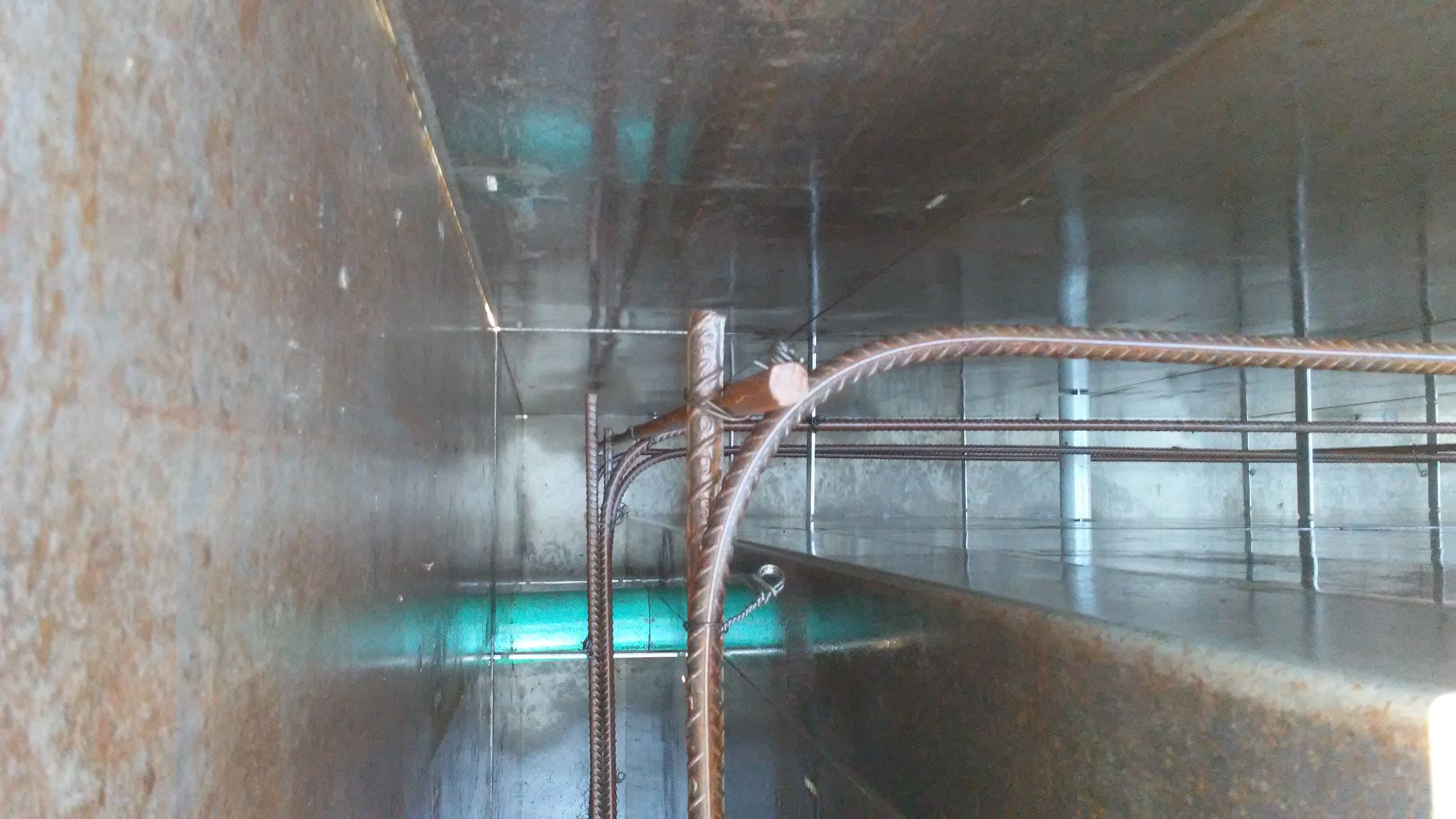
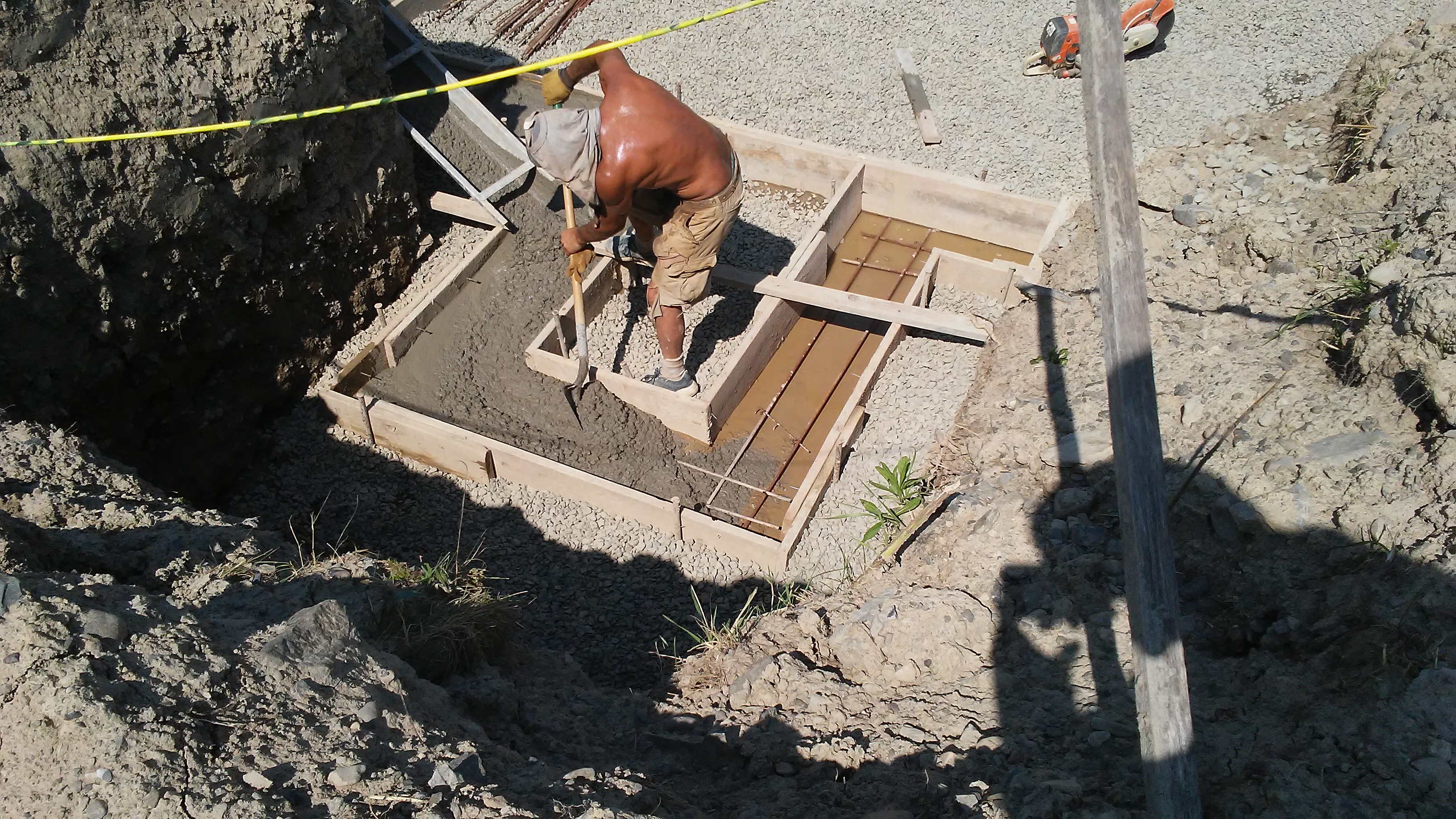
On the technical side, I’ve elected to go with cast-in-place walls for cost, making them 8″ thick so there is plenty of “bearing space” for the I-beams that constitute my floor supports. These will run underneath the SIP flooring to provide a relatively low cost and low labor support structure that will prevent floor sagging. I may at some point share some of the details of the engineering calculations for the beam strength here, but the short form is that spanning 24′ with wood would require huge timbers or manufactured wood beams that are much more expensive and not much more renewable than iron, and splitting the distance with a single 27′ beam and 12′ joists would have more susceptibility to the kind of “droop” that I’m experiencing in my own home, where doors need to periodically be adjusted so they latch properly. It seems like steel beams are rarely used in residential construction, but I’m not entirely sure why not.
I explored the use of precast stairs, but found out that the maximum opening they would allow is 39″ wide, which would significantly limit the size of tanks and other items I might want to move into the basement. It would also potentially need to be longer than the 6’4″ shown on the plans, which would make the stairs at risk of coming too close to the lot line. Bilco’s standard “Size C” door will allow for a full 4′ wide staircase, which I’ll then have to build.
F – 1: First Floor
Because I’m building an accessible home, all the living areas are on the first floor. Two bedrooms of 100 sq feet take up the east; an accessible bathroom is centered on the north wall; a large living/dining room area is at the southwest, and a small galley kitchen begins just after the front entrance at the northwest.
The layout optimizes the appliances that need water and drains (kitchen sink, bathtub, bath basin, toilet, and clothes washer) within a very small area, which will reduce the heat losses for hot water and the overall plumbing materials cost. The stove is at the outside edge to allow it to be directly plumbed with an external propane tank.
F – 2: Second Floor
This floor represents an L-shaped area of extra floor space. It won’t be accessed by stairs, but rather by a ladder of some sort. Some might choose to use it for storage, others as a play area for kids (it will have a railing around it), and others as an office. Because it’s not accessible like the first floor, I didn’t want it to have any necessary functions, but getting a good roof slope for solar more or less automatically produces a space here and I thought many would find it useful. There’s a small area at the southeast that is so low (below head height even for kids) that it’s not useful floor space, but some mechanicals (such as a heat-recovery ventilator) could conveniently be installed here.
M – 1: Electrical
This sheet shows the placement of various electrical fixtures on the first floor. It includes the placement of various low voltage LED lights, low voltage (24VDC) electrical outlets, and the conventional 120V outlets and switches as required by code. What it does not specifically cover is how the outlets and switches are wired to two different service panel – a primary 150A service panel and an auxiliary smaller (probably 60A) subpanel for “critical loads” which can be supplied from a solar battery bank inverter. I’ll write about these details in a separate blog post.
S – 1: Sections
These fun little details show cross-sections of three portions of the design: the roof, the basement wall and first floor, and the slab/footer. The roof details show how the different layers of insulation (which together add up to approximately R-53) are installed, which prevents condensation within the cellulose insulation. The basement wall details show the relationship between the footer, footer drain, basement slab, wall, backfill, I-beams, SIP flooring, and SIP walls. These details help identify how the structural components work together and also identify particular elements which need to be purchased and installed such as the “mud sill” and “rim joist” boards. Finally the slab/footer NEC detail reflects the (relatively new) requirement that portions of the foundation which are in electrical contact with the ground must now have their own ground connections, in addition to the normal requirements for grounding rods.
W – 1: Schedules
This shows the window and door “schedules” that list the particulars of the windows and doors to be installed in each location. Although I’ve listed preferred manufacturers here, this piece of the design isn’t 100% set in stone as the availability of different windows from different companies seems to vary a lot over time. One of the key elements is the fact that the bedrooms must have “egressible” windows with a significant clear area (5.7 ft²) through which residents can evacuate and/or firefighters can enter. In addition to the mandatory egressible window in each bedroom, I’ve also included one “E1” window in each bedroom, which meets the requirements only on the first floor (clear area 5.0 ft²).
N – 1: Notes
This page covers a lot of technical details which are better stated in text than in drawings, ranging from the general “do the work according to code” to details like the structural lumber stress values and the requirements for smoke and carbon monoxide detectors.
