Jul 2020: Up the Ladder to the Roof

When I was in college, The Nylons were very much in vogue.  I am sure it never occurred to me at the time that I might be climbing said ladder for the purpose of building said roof.

Cutting rafters is at lot of science and a small amount of art.  I learned the technique many years ago when I was drafted for the job during the construction of our community’s horse “run in” (think of it as half a barn).  It involves a lot of work making cuts known as “birdsmouths“; if you were to try to place a rafter without such a cut on top of the beam and top plate, what it would do is simply slide off (and hopefully not fall on anyone).  To avoid having the rafters naturally pulling away, they need to be resting on a horizontal surface.  The top of the beam and the wall plate are horizontal, and the birdsmouth cut—which looks like it’s at an angle when you’re staring at an uninstalled rafter—aligns with this horizontal surface when the rafter is installed.  This is where the old fashioned carpenter’s framing square really shines.  If you know the pitch of your roof—typically specified as a ratio in inches or feet, like my 3:12 shallow north side and 8:12 steep south side—you can simply find those number of inches on the two legs of the square and find it lined up exactly at the angle you want.

Making matters slightly more particular, the cuts can’t be more than a certain depth, but have to be a certain width, and various other parameters in order to meet code.  As mentioned last month, my oversized 2x12s really only needed to be 2x10s, and allow for a slightly deeper cut.
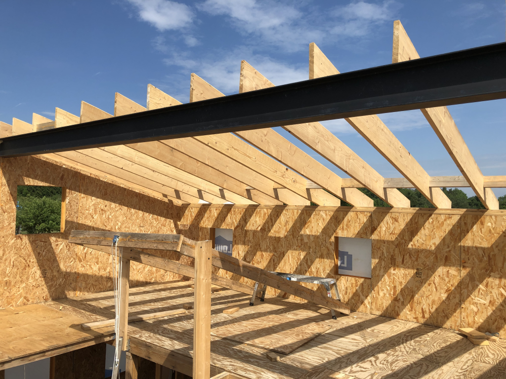
2020-07-03 North Side Rafters

The art comes in to figuring out which portions of the design you can simply repeat over and over for 13 rafters on each side, and which ones need to be carefully measured.  Art isn’t my strong suit.  I did a lot of measuring, averaging about 1h22m per rafter, for a total of almost 36 hours.  Pretty much every rafter went up once for measurement, down again for cutting, and back up again into place.  Also, until you get very familiar with it, you’ll probably find yourself turning the framing square around at least once and maybe twice for every single birdsmouth you try to mark.

Oh, and then there were those two outer rafters.  These turned out to be quite a chore, because the birdsmouths on the interior rafters caused them to fall slightly lower than the level where the cut SIP edge lay.  In the end I wound up having to do long rip cuts to adjust the rafters to match up with a level top surface.  Slightly more careful thought about the relation between the SIP cuts, inlet nailers, and beam position would have been helpful here.  Oh well, it worked.
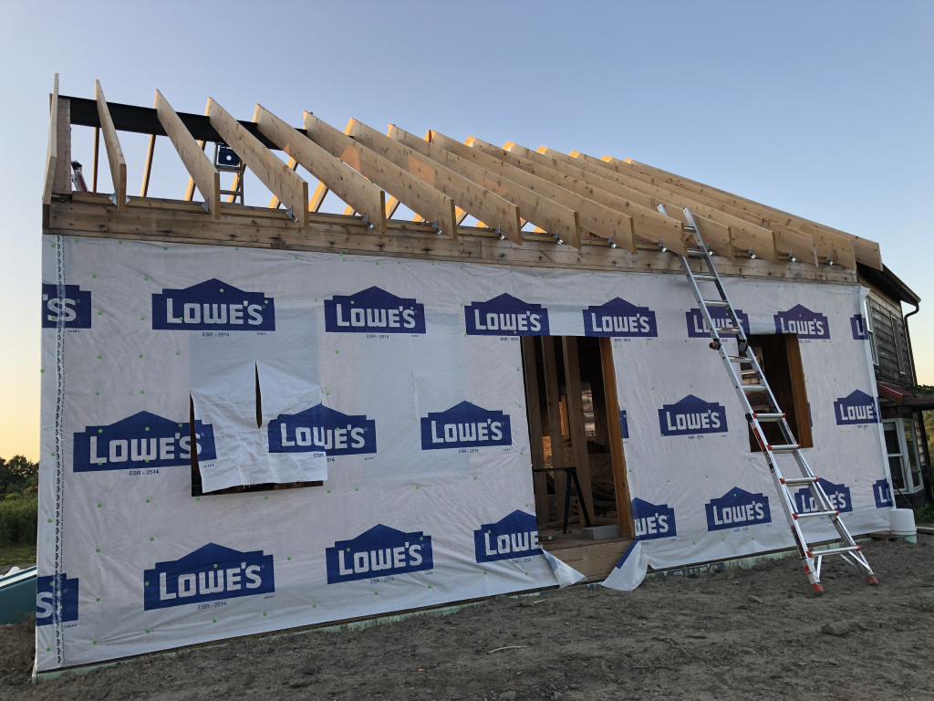
2020-07-17 South Side Rafters

After putting the rafters in place, I started on what would become another of the many facepalm manoeuvres: placing blocking SIPs between the rafters.  It seemed like a good idea—in fact, it probably was a good idea—but for the fact that I didn’t think about the need for a gap for the roof ventilation (more on that later).  I got about this far before I realized the problem:
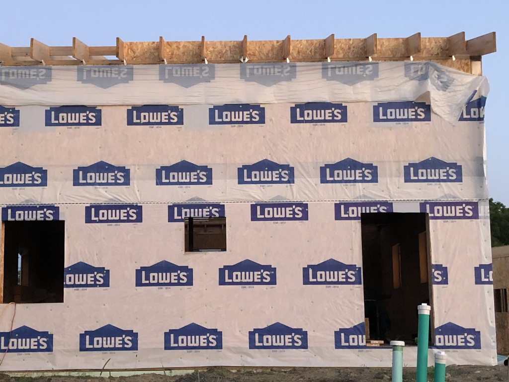
2020-07-24 Rafter Blocking SIPs

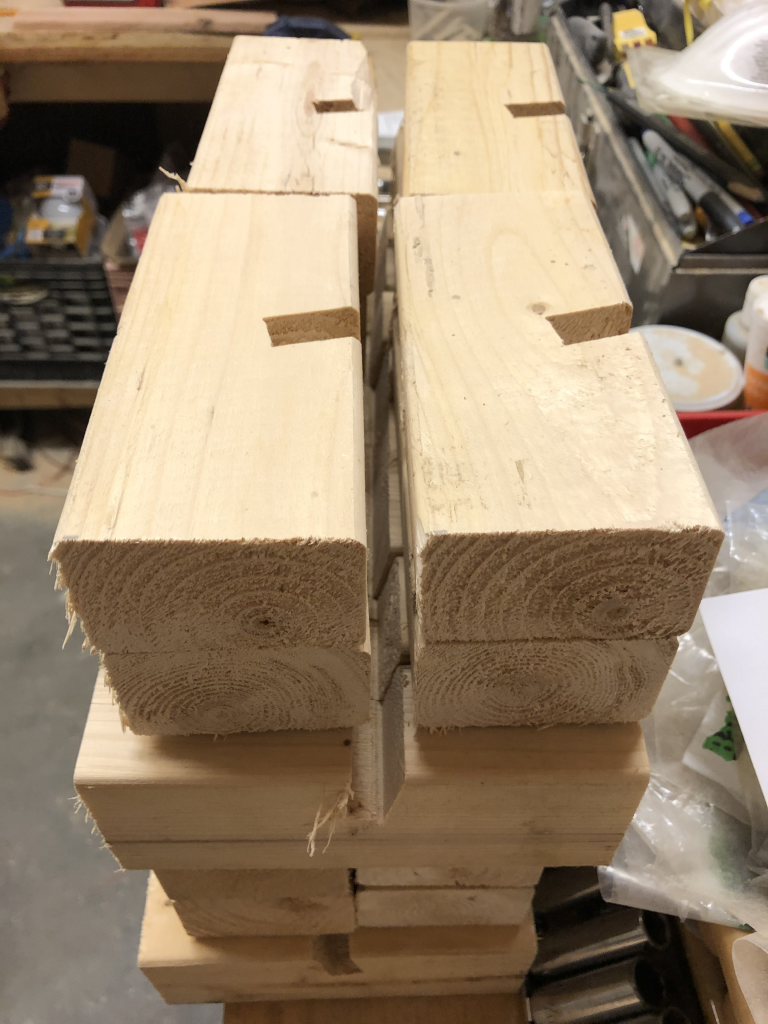
The second hand of facepalming was because that each one of those SIP blocks was a lot of work (about 22 hours).  Each one needed a carefully miter-cut 2×8 plus a lot of manually cutting foam out of the SIP; because of the angle, it wasn’t possible to use the SIP panel router.  That was a big part of the reason I decided to change strategy for the fix, rather than just cutting them down and trying again.  The replacement amounted to simply installing OSB panels, and then putting in foam board insulation with spray foam sealing after the fact.  However, the top end of these OSB panels had to be solidly anchored since they would be about 1-½” lower than the top of the rafters.  I settled on making a lot of small 2×3 blocks with angle cuts to slide around the OSB:

2020-07-28 OSB Angle Blocks

More than that.  A lot.  56 in total.

2020-08-01 Way More OSB Angle Blocks


How to make these efficiently is may actually be an interesting aside.  I cut the 2x3s down to a more manageable length (4′), and then set up a dado blade to make a cut of the right width to match the OSB (a little wider, so I wouldn’t have to deal with it binding).  But the dado blade had to be angled to match (or more accurately reverse) the angle of the rafters to meet the vertical OSB sheets.  Once again, the carpenter’s square (small version) comes to the rescue:
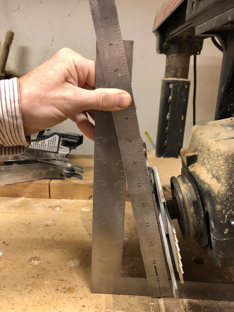
2020-08-01 Dado Blade Angle Setup

Just a word of caution: I had to take the blade guard off to swap the standard blade on the radial arm saw for the dado blade, and to set the angle.  Do what you need to be safe here.  Unplug the saw if you have to.  Put the blade guard back before you plug it back in.  Never stand in line with the blade when cutting.  You know the drill… er, the old saws… yeah.

So here’s what the old and new solutions look like side-by-side as I was pulling one out and replacing it with the other.
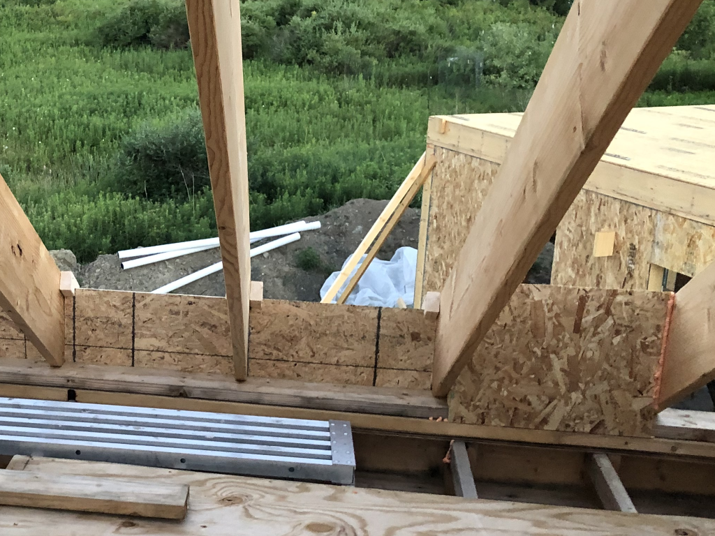
2020-07-28 Two Blocking Solutions


Avoiding Header-Aches

As I started thinking about putting in the structural walls to support the floor joists, which need to go in before the second floor can be built, I started to agonize about certain aspects of the design that hadn’t really captured my attention before.

There are two areas on the original plans where very long (eight to ten feet long) “headers” (structural supports over openings) were needed to bridge over open areas: over the kitchen (shorter span, and less weight to bear) and above the two angled bedroom doors (longer span, and greater weight).  I wanted to keep these headers limited to 2×8 members, so that they wouldn’t have to drop down significantly into the living space, but there are limits to what even a triple 2×8 can span and still provide sufficient structural support.

Floor Plan Before Wall Adjustments

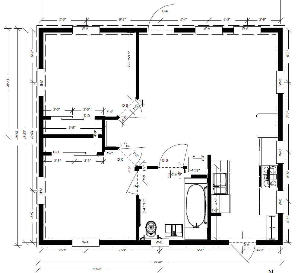
And then I found myself wondering why I had wanted those slanted doors in the first place.  I mean, they’re harder to build, they take away from the floor space in the bedrooms, they don’t actually add useful floor space to the living room… they just seemed like a bad idea all around.  Could I adjust the plan so that the doors were straight along the wall, thus providing a space between them where a vertical support (“jack stud”) could support the header?

One question led to another and pretty soon I was rethinking a lot of different things.  What did I really want to do for loft access?  Where would it go?  Was the area I had carved out for the washer/dryer actually the right size?  Were the closets the right size and optimally placed?  Did I need three doors within a few feet of each other around the bedroom and bathroom?  In the end I made a lot of relatively small adjustments, but several that I think are reasonably significant.

Raederle answered the question about the three doors with a resounding “yes”: given that the bedrooms open out onto the living area, it’s really important that at least one of the bedrooms offer a path to the bathroom without going into the common space.  Imagine your kids have guests over and you’ve slept in… do you really want to have to put clothes on to get to the bathroom in the morning?

We decided that the aesthetic of a spiral staircase would add a lot of appeal to the interior design.  This would take more floorspace (12-15 sq ft) than a drop-down attic stair (8-10 sq ft) but a whole lot less than a conventional staircase (33 sq ft), and despite the cost it would probably be worth the difference in making a more pleasant and usable space.  The placement of this couldn’t be after-the-fact, since it would have to come in to an area where the ceiling height was at least 7′ (a maximum of 18″ south and 48″ north of the centerline).  In the end, it pushed the doorway of the second bedroom to the south end of the wall.  (One can argue that this slightly improves egressibility since it opens out right onto where the back door is located.)

I tried adjusting the closets to go adjacent instead of back-to-back.  However, this created issues with the placement of the BR1-LR door and with ensuring the accessibility of the bathroom, and so instead I just stretched out the wall between them.  The combination of the door and closet placement now means that BR2 could more easily accommodate two twin beds, by poking one into the corner created by the closet.

A little fine-tuning on the loft design now brings the northern loft area further out over the kitchen, which gives better access to the west wall window in the loft.  (I may also take advantage of this to increase the kitchen cabinet sizes a bit on the right of the sink, though I haven’t addressed this in the design.)  There’s a small area between the staircase and the bathroom where the loft floor meets the staircase platform which is actually cantilevered out, but it’s under 2′ long and I don’t think it will be aesthetically objectionable since it’s at ceiling height.

I ensured that the washer/dryer space was big enough for the larger (4.3 cu ft) unit rather than the smaller (2.8 cu ft) unit that I had originally projected; this means it will fit a wider range of solutions.

I adjusted the west wall of BR2 to be a 6″ wall instead of a 4″ wall, to provide extra structural support for the flooring and make it easier to route mechanicals.  This wall is intended to come in partially overlapping the steel I-beam in the floor, so that it’s easy to route mechanicals to the side of the I-beam, while still being able to bear most of the weight directly on it.

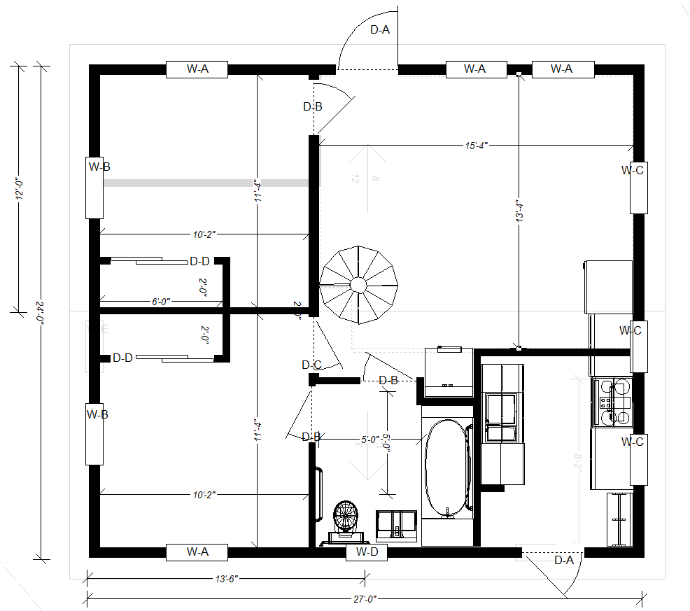
Below is the resulting changed plan.  It probably doesn’t look much different unless you’ve been spending as much time thinking about this as I have… but it means that there are no headers on the west bedroom wall that exceed the width of a door, and the header over the kitchen falls into the range where three or four 2×8’s can easily provide the required support.

I needed to get this nailed down because one of the next steps is to actually lay out the placement of these walls on the subfloor, so that I can begin constructing the structural walls and then complete the rim joists and floor joists of the second floor.

Floor Plan After Wall Adjustments

Re-floor-mation Completed

Between Mar 1 and Apr 14, I completed the process of removing the old subfloor and replacing it with a new, lower subfloor, as described in my Floor Mark 2 post.  All told, I spent:

  • 89 hours constructing the original floor (2019-10-08 to 2019-11-21)
  • 12.5 hours in mitigation/drying efforts (2019-11-21 to 2019-12-13)
  • 32 hours removing the original floor (2020-03-02 to 2020-04-06)
  • 59 hours installing the new floor (2020-03-02 to 2020-04-14)

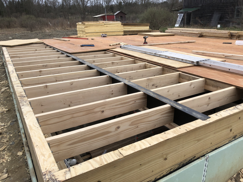
I finished getting the new joists installed:

Floor joists
Final section of new floor joists


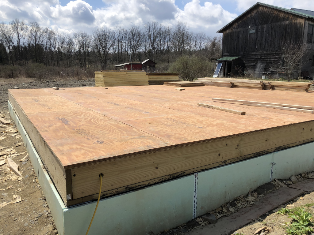
…and reinstalled the subfloor the same day (although I didn’t get the photo until the next morning):

New flooring
New flooring finished


Then, I was ready to start on SIPs.  More on that in the next post.

Do Over: Floor, Mark 2

Since part of my goal is to document the process of construction, it’s time to declare my first major oops.  Maybe this will save someone else from doing something pointless and wasting time and money.  Sigh.

I am not happy with my floor implementation.  It feels solid and well insulated, but there are numerous issues with it that have led me to decide to start over.  In the end I expect I’ll waste about $600 and maybe a week worth of labor, but I think the end result will be better.

First, I wanted to nominate Terry S. for the “you called it” award on water.  Even with one layer of house wrap, fully taped, and not one but two 30×30′ tarps tented up and covering the floor, it is still basically raining inside every time the weather turns warm or launches into a downpour that melts the snow.  While I’ve had builders assure me that the water will just run through, and it will dry out, and it will all be fine, I’m not certain enough to trust putting the rest of the house on it without checking.  And checking means starting to peel up the subfloor so I can look inside, and once I start that if it looks bad, I’m going to need to redo things anyway.

But that by itself could just be a bit of maintenance in the spring.  No, there are a lot of other problems that have combined to make we want to start over on the flooring.

  • Elevation: because of the additional 6″ of height added by the flooring (which would of course have been there with SIPs as well) making the home accessible is turning out to be a lot more difficult that I would have liked.
  • Structural: the bottom inlet nailers for the wall SIPs would have been mounted to the floor stack, which itself is not really a tested structural element.  (SIPs would have been better, but not ideal.)
  • Levelness: in my rush to get the floor in place before the winter, I didn’t do a great job of shimming around the I-beams to bring the rim joist level up to the I-beam level.
  • Mechanicals: with the insulation sandwiched between the two layers, any mechanicals (plumbing and electric) going through to the basement would have to be cut through both layers of board plus insulation.
  • Water damage: may or may not have occurred.

So, I’ve come up with a new plan, and by choosing to go forward despite the possibility that the current floor is “sound” (with respect to the water – all the other issues would still stand), I have the opportunity to implement a good fraction of it (the first three steps) from inside the basement during the winter, so there will be less of a scramble to do the added work when spring comes.

  1. Cut 2×8 joists to fit between (and perpendicular to) the I-beams.  Notch these at each to a depth closely matched to the flange thickness of the I-beam, so that when assembled the top of the joist and I-beam will be flush.  (This addresses the elevation issue: subfloor will eventually sit 6″ lower.)
  2. Remove screws from bottom of current assembly.
  3. Insulate rim joists.  (May need to wait depending on other steps.)
  4. Strip off and stack the subfloor boards.  (If the subfloor was water damaged, then it would have needed to be replaced anyway, but if it’s OK I hope to be able to reuse it since I’ll be screwing back down to identically aligned joists.)
  5. Pull out and stack the rockwool for reuse.
  6. Strip off the 2×6 and 2×4 joists and the PIR.  (We’ll have to see what order of operations works best for this.)  Stack PIR for reuse.
  7. Strip off and stack the PT plywood.  (Need to determine if it can be reused elsewhere in the project; otherwise perhaps it will show up on Craigslist.)
  8. Correct the shims on the rim joists to as near flush with I-beams as practical.  (This addresses the levelness issue.)
  9. Finish mounting east and west joists with joist hangars from rim joists.
  10. Reinstall subfloor.
  11. Put off reinstalling insulation until after mechanical work is done.  (This addresses mechanicals issue.)
  12. Install inlet nailers with structural screws to rim joists.  (This addresses structural issue, and is the first step of the work I would have started in the spring anyway.)

It seems like a lot of steps, but it feels like I should be able to do most of them in less than a day.  So far I’ve completed the first eight of the 7′ joists and eight of the 4′ joists, and about 20% of the screw removal.  While I was at it, I also restacked some of the stored lumber in the basement so that it’s not directly under the drip edges.  The time spent has been about 3 hours so far.

For photos see my Apr 5 post.